
This page describes how I managed to fix my Commodore 1351 Mouse by tuning the gain on the optical encoders. Highlights include:
- Links to useful resources available online.
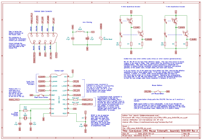
- A new, detailed schematic to help others working with this mouse.
- A walkthrough of steps I took to isolate the problem.
- An explanation of how to adjust the gain on the quadrature encoders by choosing the right resistors.
- A cute way to stash trimpots inside the mouse, to make it easier to tune the gain in the future.
I'm a beginner at a lot of this stuff, so I have to give huge thanks to my friends for helping me along the way, and humoring my endless noob questions.
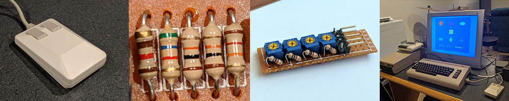
I've been on a retro computer repair kick lately, and while rooting through boxes in the basement, I was amazed to stumble on the Commodore 1351 mouse from my childhood. It was in surprisingly good shape:
Sadly, when I plugged it into my Commodore 64, all was not well. The mouse buttons worked, but there was no cursor movement at all. A Google search quickly found a number of forum posts and YouTube videos of people with similar problems, but most of them had limited success fixing the issue.
Armed with a soldering iron and the enthusiasm of a really ignorant beginner, I set out to fix it.
I was able to find some useful resources on the web:
- User Manual for the 1351 Mouse (text version).
- Spec for the MOS 5715 (the chip at the center of the 1351 mouse).
- Patent for the method of connecting a mouse through the Commodore control port.
- Unofficial Schematic for the A0101930 Rev A version of the PCB in the mouse, reconstructed by Frank Kontros.
The last one was of particular interest, since my mouse has the Rev A board.
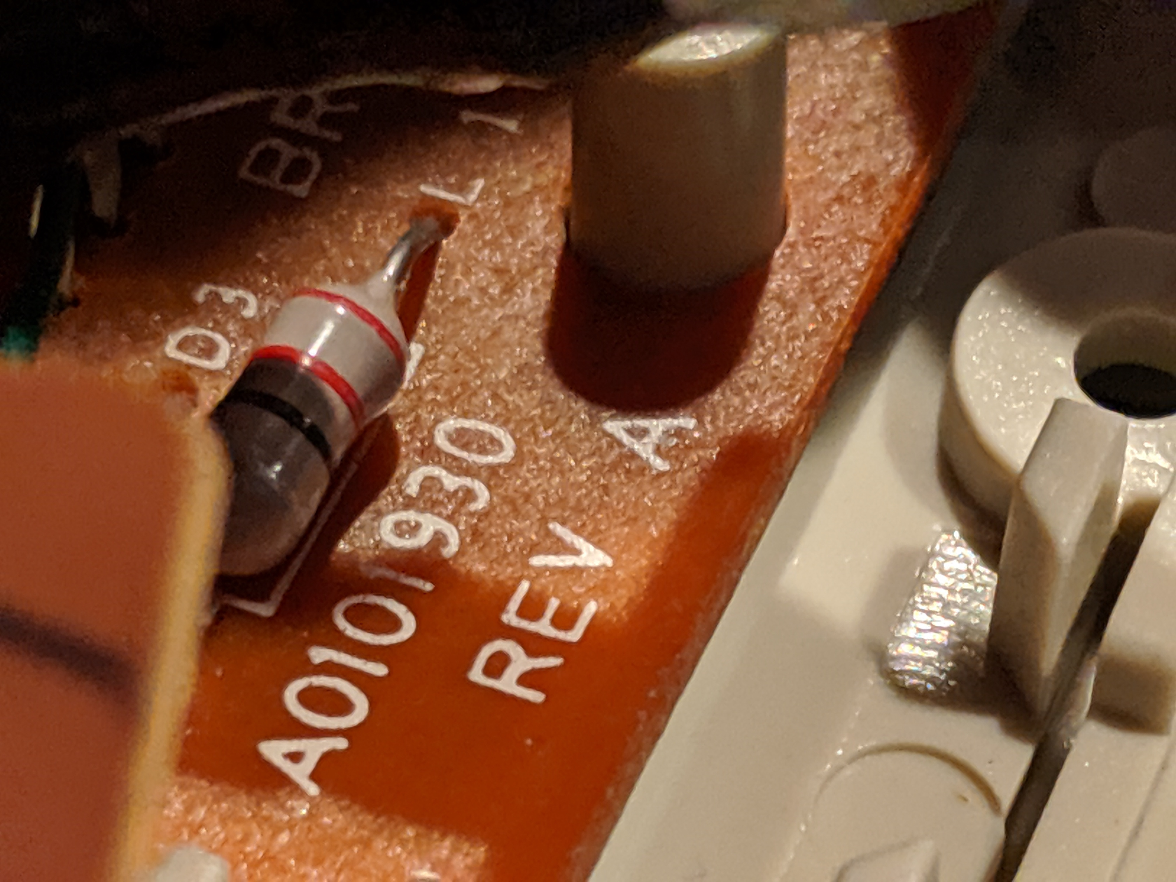
Frank's schematic really helped get me started. It oriented me to the layout of the mouse and gave me a sense of how to proceed with debugging. However, I ended up making a new schematic, in part to correct some minor errors (incorrect units on some components, several pins swapped on the central chip) but mostly because of the confusion around the pull-down resistors that I discuss below. Also it was a good opportunity to practice with KiCad.
My first step was to make sure the cable was intact. See my schematic for the pinout of the cable connector. The numbers printed on the top of the board (and the wire colors) correspond to the cable pinout. I was able to test continuity with the solder joints on the underside of each one:
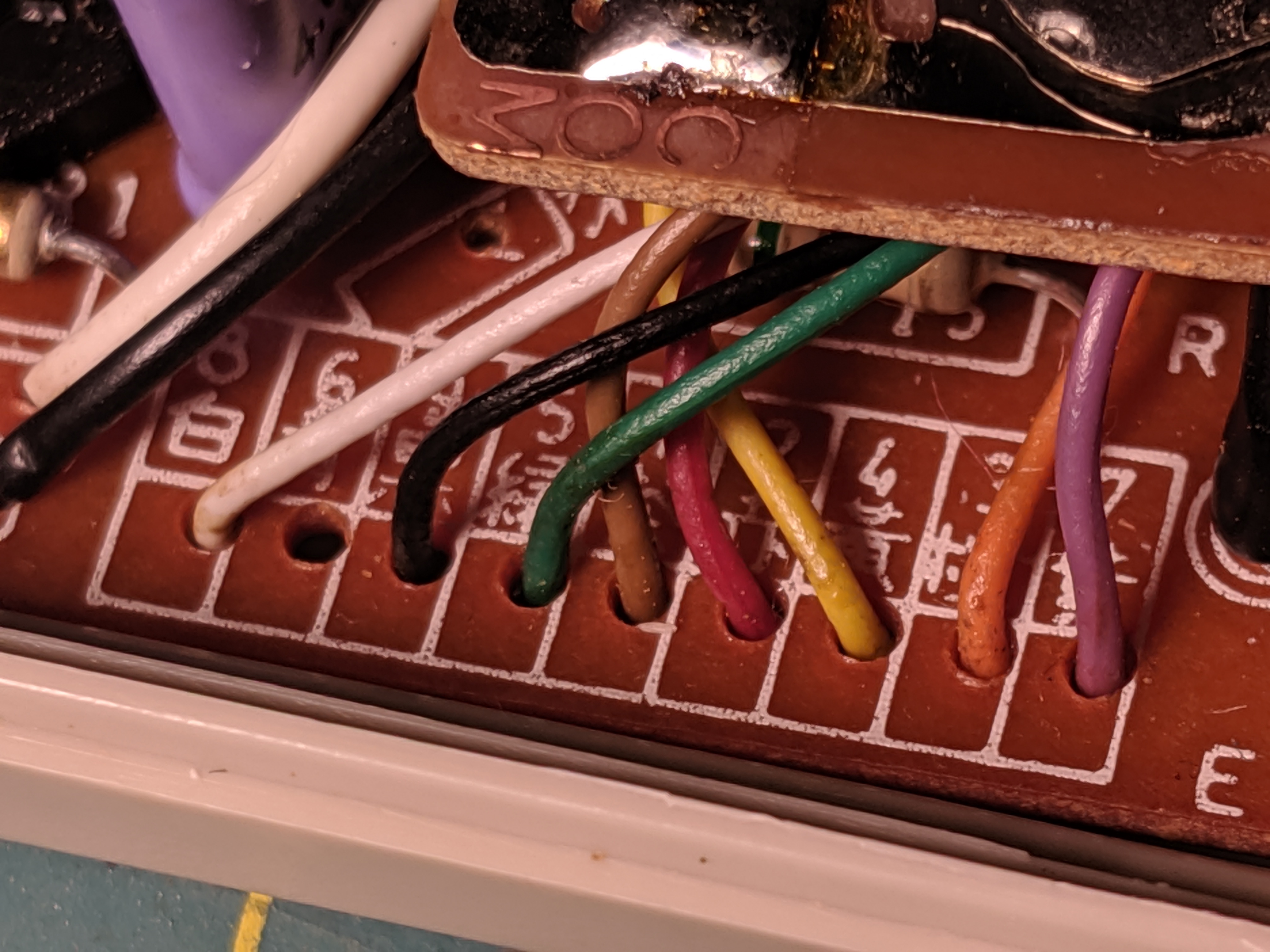
Note that wire 6, used by mouse button 1, doesn't connect in its labeled spot. It goes straight to the daughter board for the buttons, so the easiest place to test its continuity is on this exposed trace:
In my case, the connections were all good, which means the cable was not the problem.
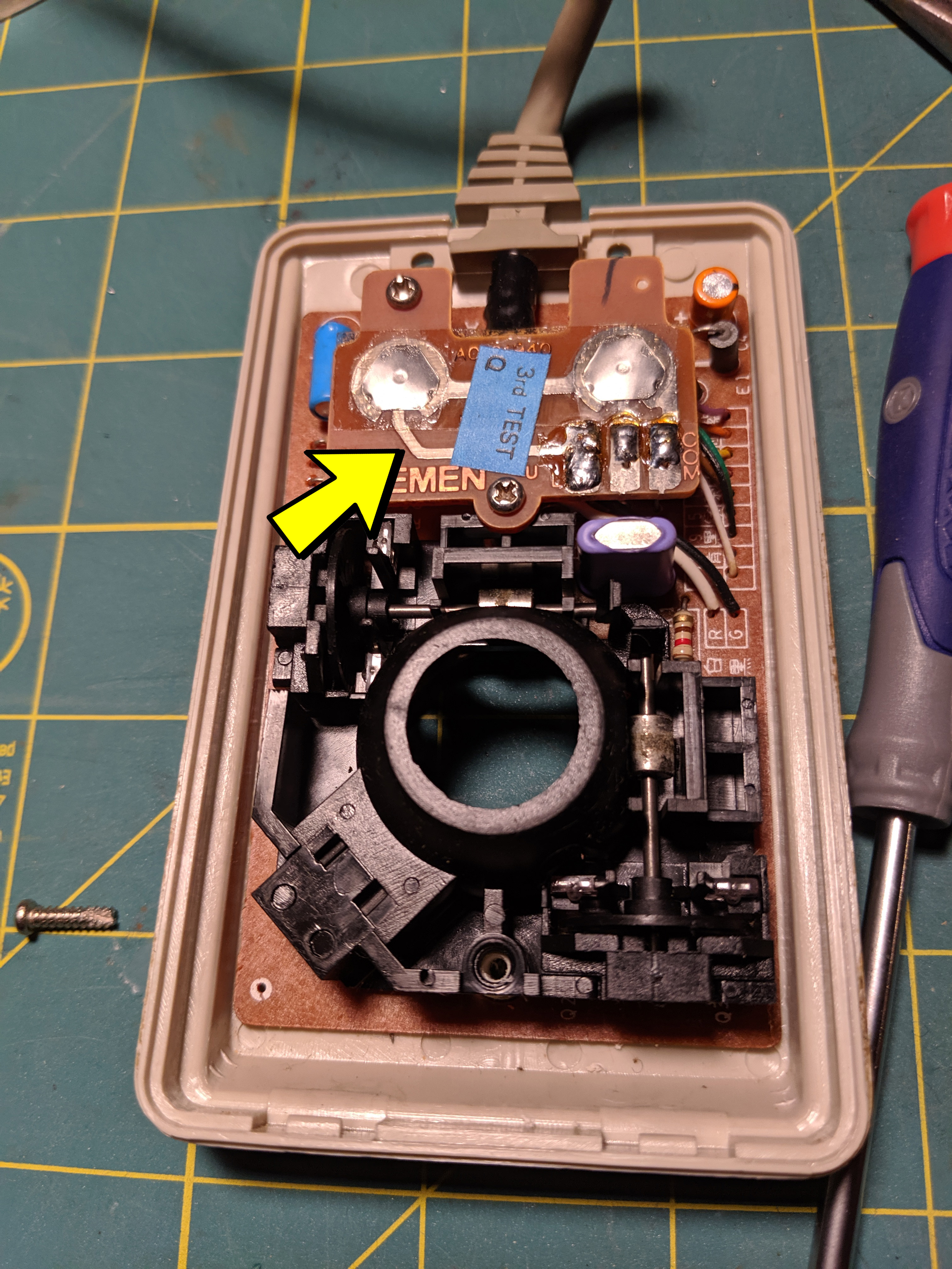
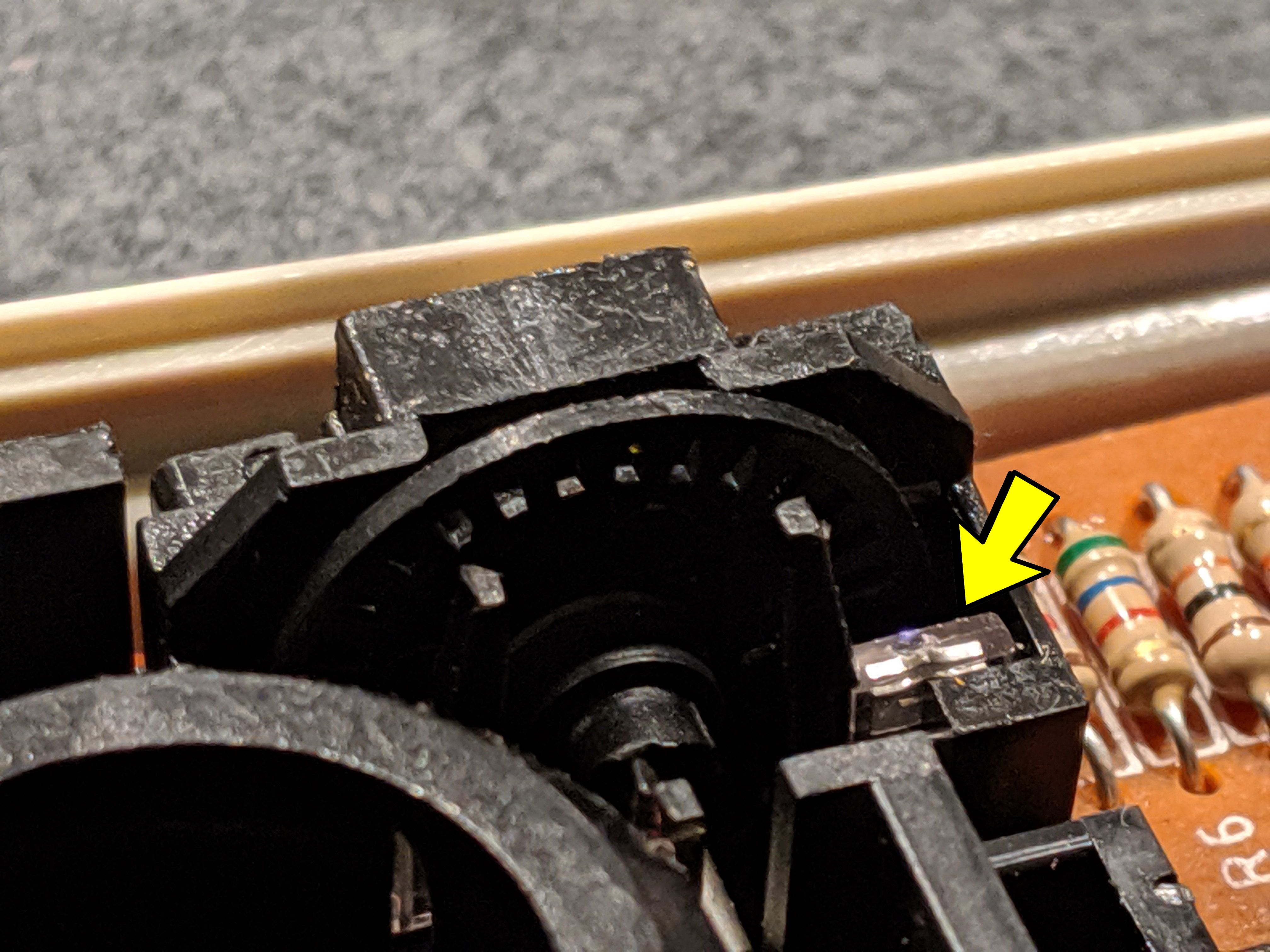
Mouse movement is detected in the 1351 with two quadrature encoders, one for the X axis and one for the Y axis. Each quadrature has two emitter/receiver pairs, shining through out-of-phase slots in a rotating wheel. You can see an emitter here and the slotted wheel; the receiver is hidden inside the plastic enclosure on the far side of the wheel.
There are four emitters total, and they're located here:
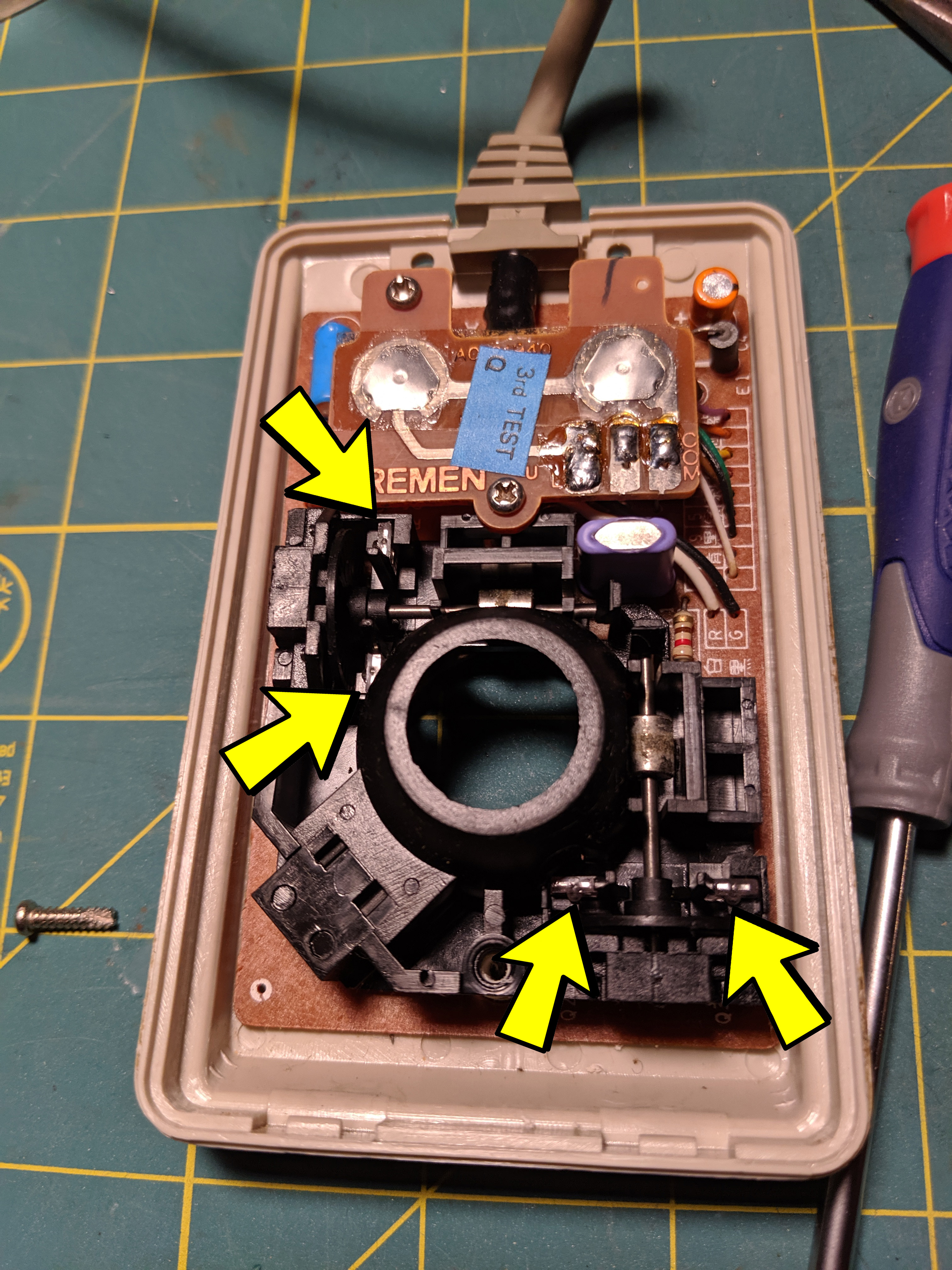
These are infrared LEDs, so you can't see their light by naked eye. Luckily, they're visible to CCD-based digital cameras. So I powered up the mouse, turned off the lights, and aimed my phone camera at it in the dark. It was sort of magical, seeing the live view on my phone screen of lights that I couldn't see with my own eyes.
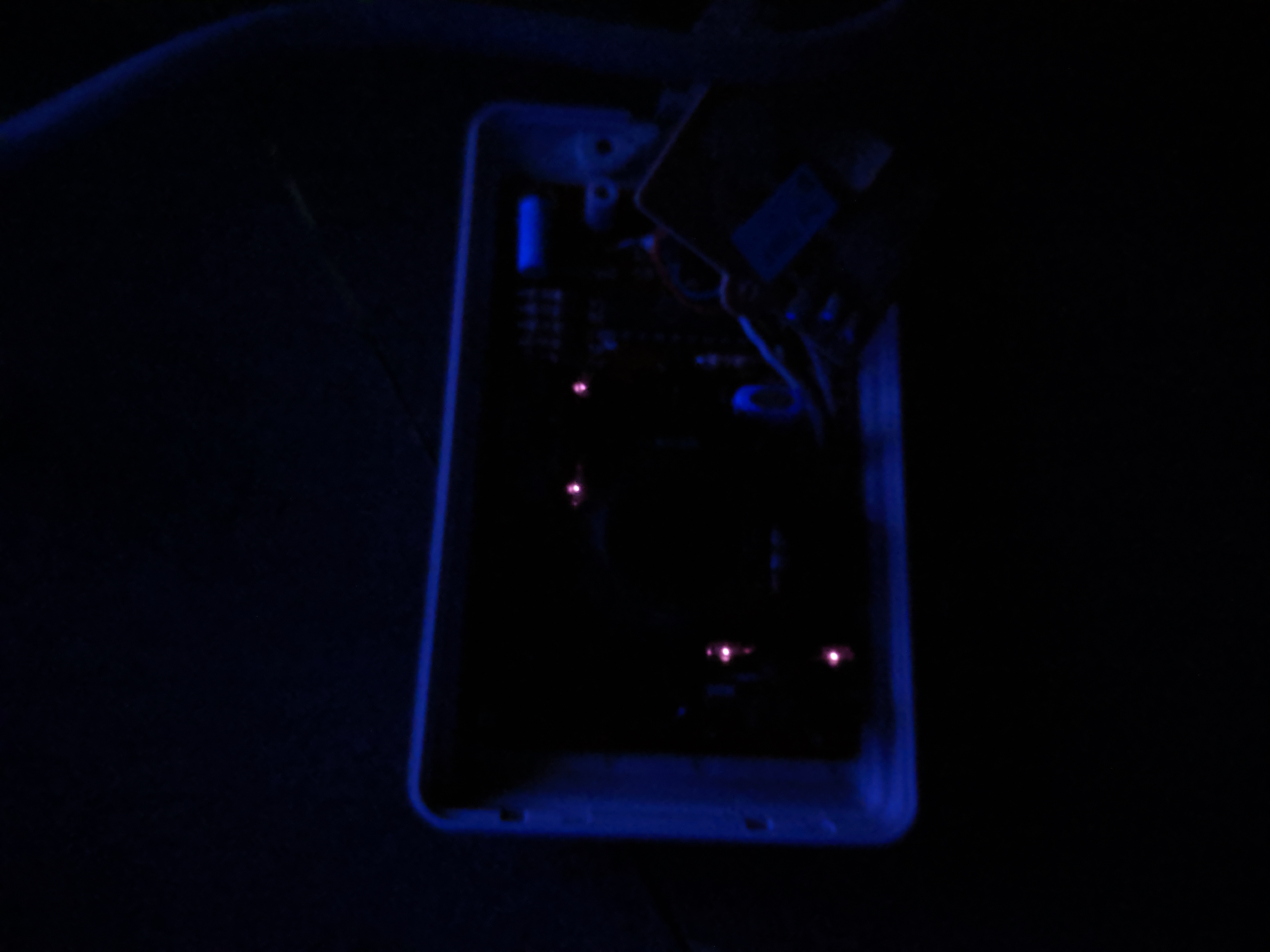
Since all of the LEDs looked fine (or at least they were shining at about the same brightness), I moved on to the next step in the signal chain.
Each LED shines on a phototransistor. As the mouse moves, the slotted wheel alternately blocks and reveals the light, causing the output of the phototransistor to alternate between low (-0.3V to 1V DC) and high (4V to 5.3V DC). If any receiver is unable to alternate between these levels, that axis won't work.
So I checked the voltages coming out of the receivers. The phototransistors output to pins 1-4 of the MOS 5717, so I checked the voltages at those pins. Later I realized it would have been easier to just check the voltage across the corresponding pull-down resistors, R6, R7, R8, R9.
Moving the encoder wheels by tiny amounts, I was able to work out the max voltage seen on each line. This is possible with a multimeter, but much easier on an oscilloscope. Here's what I saw:
- Pin 1 (X_QUAD0): 4.6V
- Pin 2 (X_QUAD1): 1.7V
- Pin 3 (Y_QUAD0): 4.7V
- Pin 4 (Y_QUAD1): 2.7V
So two of my four receivers were sending weak outputs, one on the X-axis, one on the Y. That explains why I was seeing no mouse movement! But what's causing the discrepancy in voltages?
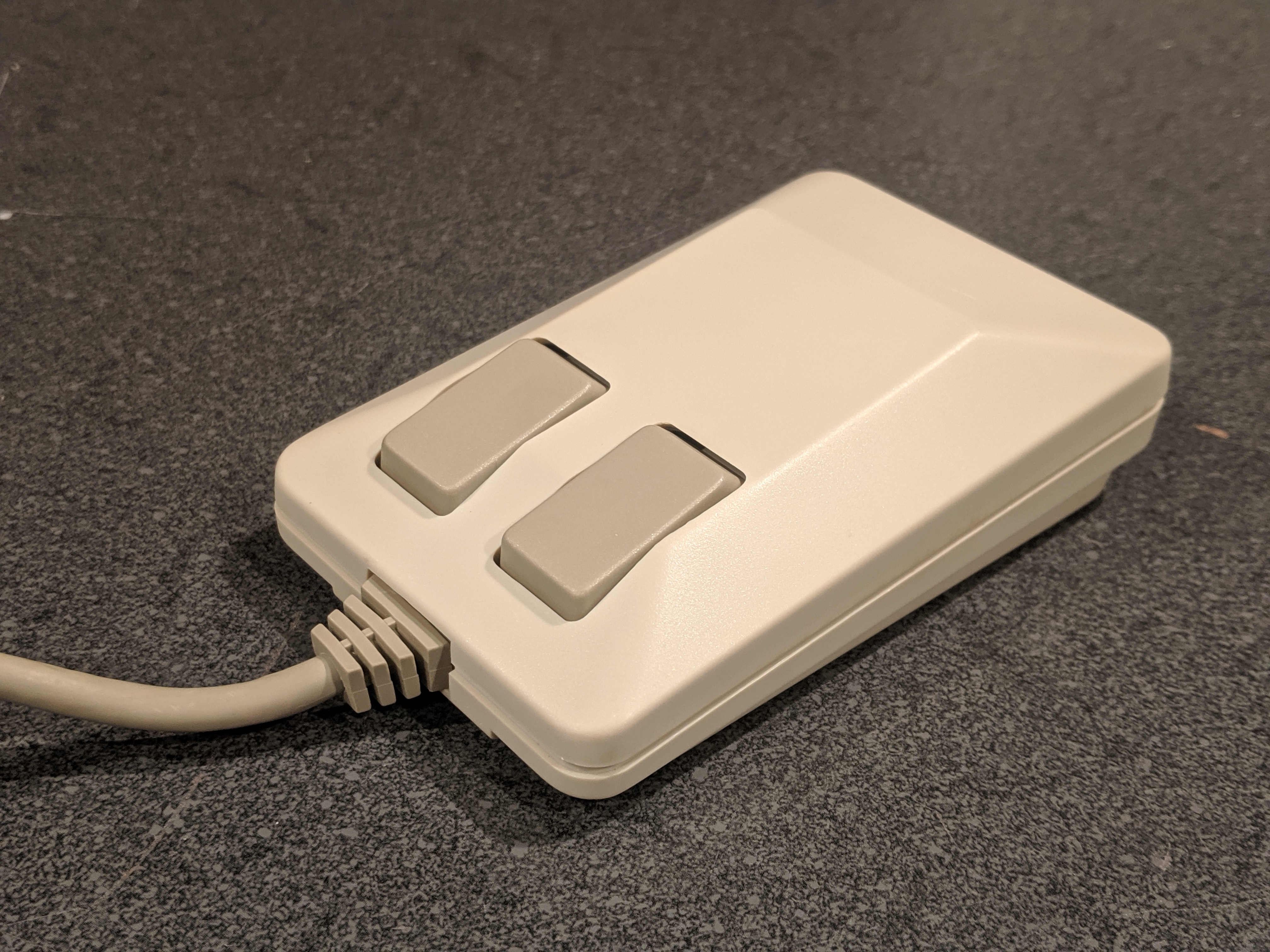
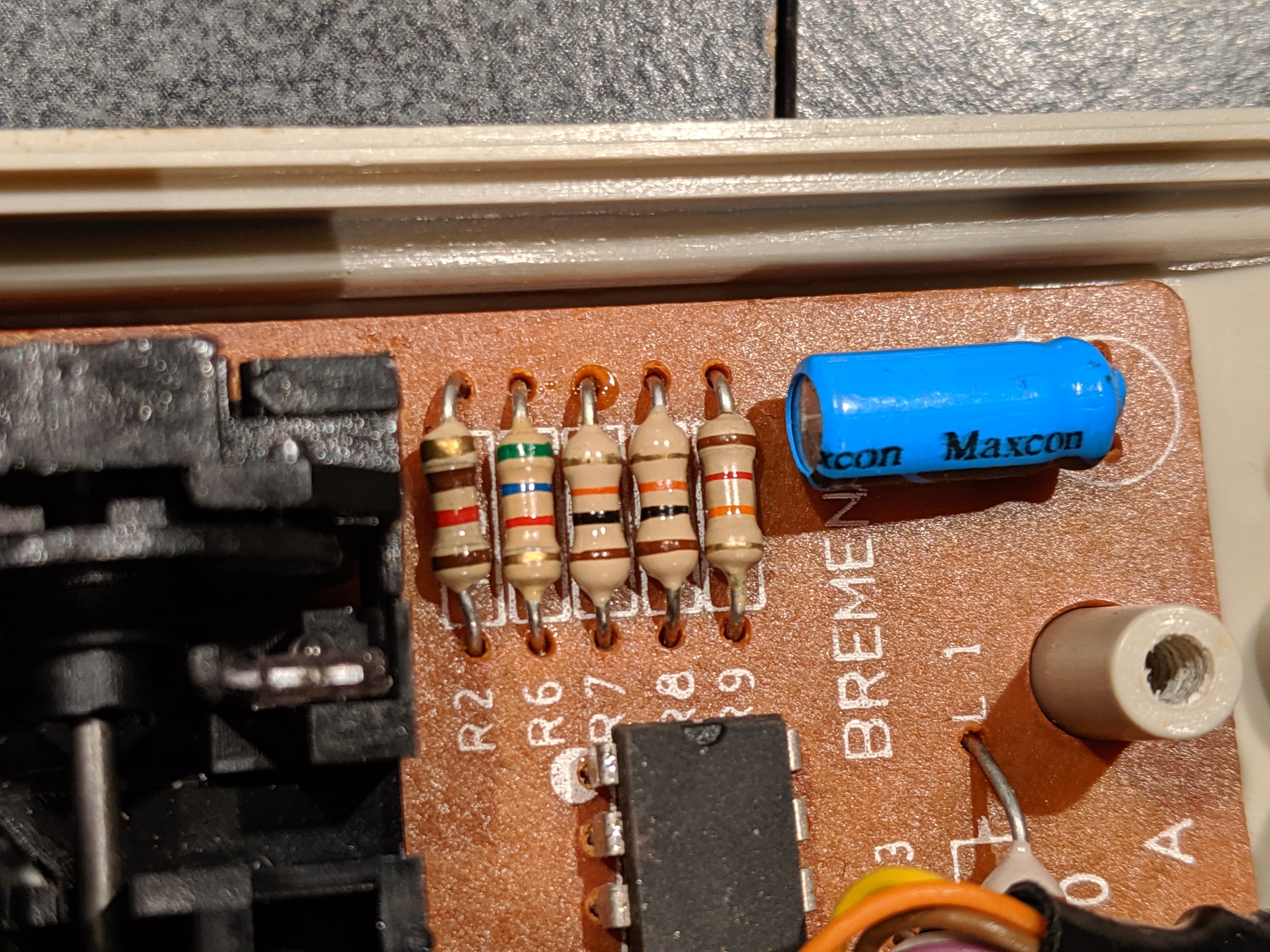
Then I noticed something suspicious: in each quadrature, one line was good and one was bad. And according to Frank's schematic, the good lines were connected to 6.8kΩ resistors, and the bad ones had 15kΩ resistors. Could this have anything to do with it?
There are a number of forum posts expressing confusion about R6, R7, R8, R9. Why are there two different values in each quadrature? A few people noticed the resistors in their own mouse differed from the schematic, and replaced theirs to match the schematic. Generally this didn't make things better.
After mulling this over for a day, I finally realized what was going on. What if the resistors' values in that schematic aren't the "correct" ones, but just the ones that happened to be in Frank Kontros' mouse? Maybe they're different in every mouse. Indeed, when I finally bothered to decode the values in mine, I found:
- R6 (X_QUAD0): 5.6kΩ
- R7 (X_QUAD1): 10kΩ
- R8 (Y_QUAD0): 10kΩ
- R9 (Y_QUAD1): 12kΩ
Not only different from the schematic, but a totally different pattern. So I had a theory: these resistors were chosen in the factory, not based on a "correct" value, but tuned for the specifics of each mouse being assembled. Maybe variation in manufacturing (cheap plastic parts) forced Commodore to hand-pick resistors to achieve consistent voltage on each line. A moment's googling confirmed that the pull-down resistor's value adjusts the gain of a phototransistor, so this all made sense.
Most likely, the sensitivity of my mouse has degraded over time from some combination of:
- Dirt or obstructions on or between emitter and receiver. (I eliminated this by cleaning both with isopropyl, and blowing out the area with compressed air. No luck.)
- Worn out emitter (LED) not shining bright enough.
- Worn out receiver (phototransistor) not responding to light as it should.
- Distortion in the plastic parts of the enclosure, which can lead to misalignment.
Instead of replacing those parts, I figured, I could just increase the gain on pins 2 and 4 by choosing the right resistors!
This page suggests that there's a linear relationship between the value of the pull-down resistor and the sensitivity of the phototransistor. If this is true, I can calculate the correct resistance with:
Rnew = Rold * Vnew / Vold
where Rnew is the new resistance we need, Rold is the old resistance, Vnew is the max voltage we want to achieve, and Vold is the max we're currently achieving. I arbitrarily picked 4.6V as my target, and calculated:
- R7: Rnew = 10 * 4.6 / 1.7 = 27kΩ
- R9: Rnew = 12 * 4.6 / 2.7 = 20.4kΩ
I suspect that using these values would have worked, but then a friend suggested a better approach.
- Put a 100kΩ trimpot and a 1kΩ resistor in series on a breadboard. (The resistor is just to prevent you from shorting it if you tune the trimpot too low.)
- Tune the trimpot so the combined resistance is 5kΩ.
- On the mouse, desolder the resistor for a line whose voltage is too low (eg R7 on mine).
- Solder two wires in its place, and connect them to the breadboard around the trimpot/resistor series.
- With the mouse under power, measure the max voltage between the two wires while moving the encoder wheel slowly. Adjust the trimpot a tiny amount, and keep moving the encoder wheel to see how the max voltage is affected. Continue this until the max voltage reads 4.6V DC. (Again, an oscilloscope makes this much easier.)
- Remove power, remove the wires from the breadboard, measure resistance across the trimpot and resistor in series. That's the resistance you need for this line.
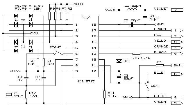
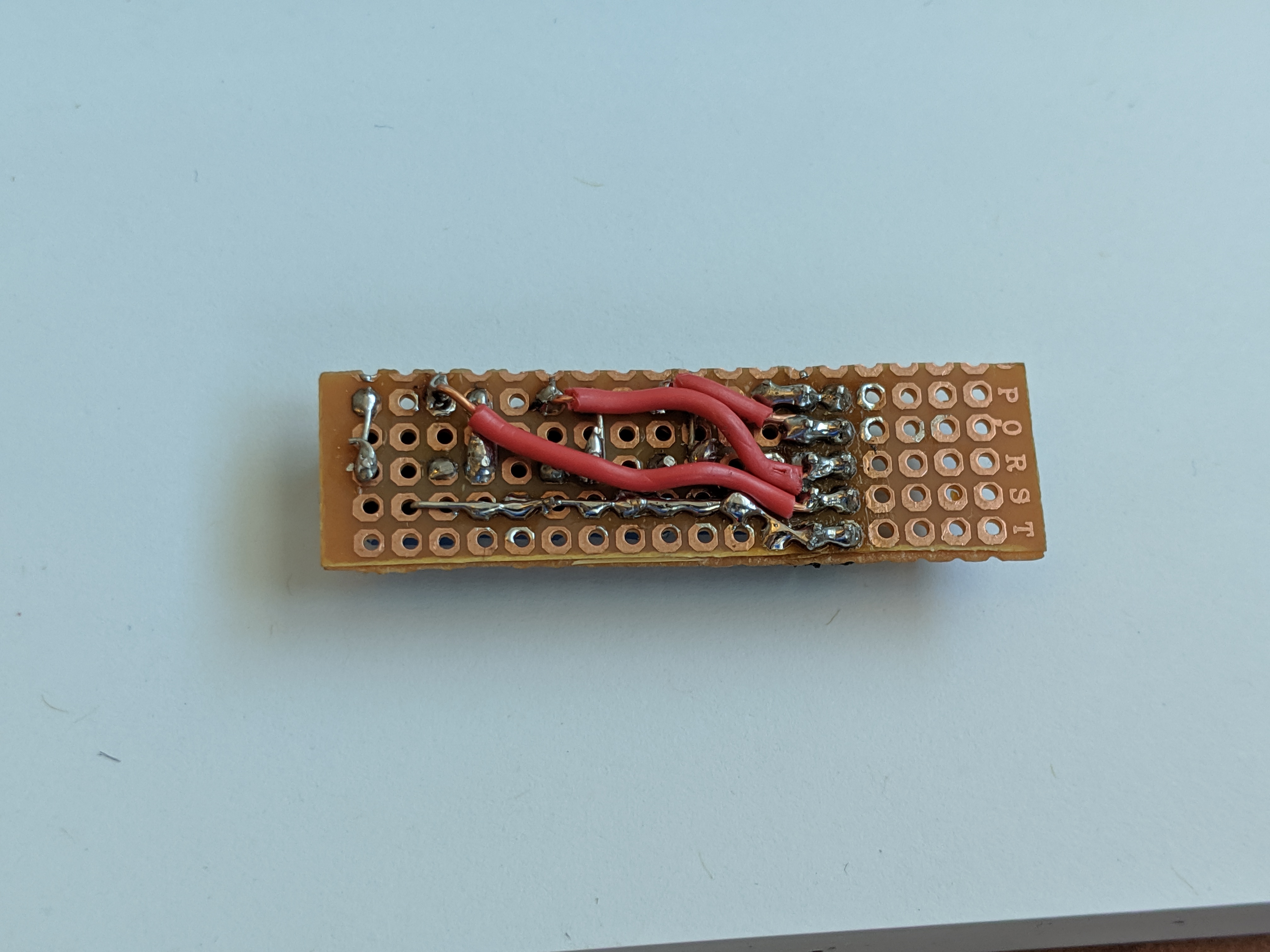
I decided to go one step better. I reasoned that if the mouse sensitivity has degraded over the years, it might do so again. I might need to do this same adjustment in a few years. I really wanted the gain adjustment to be onboard, so I made this:
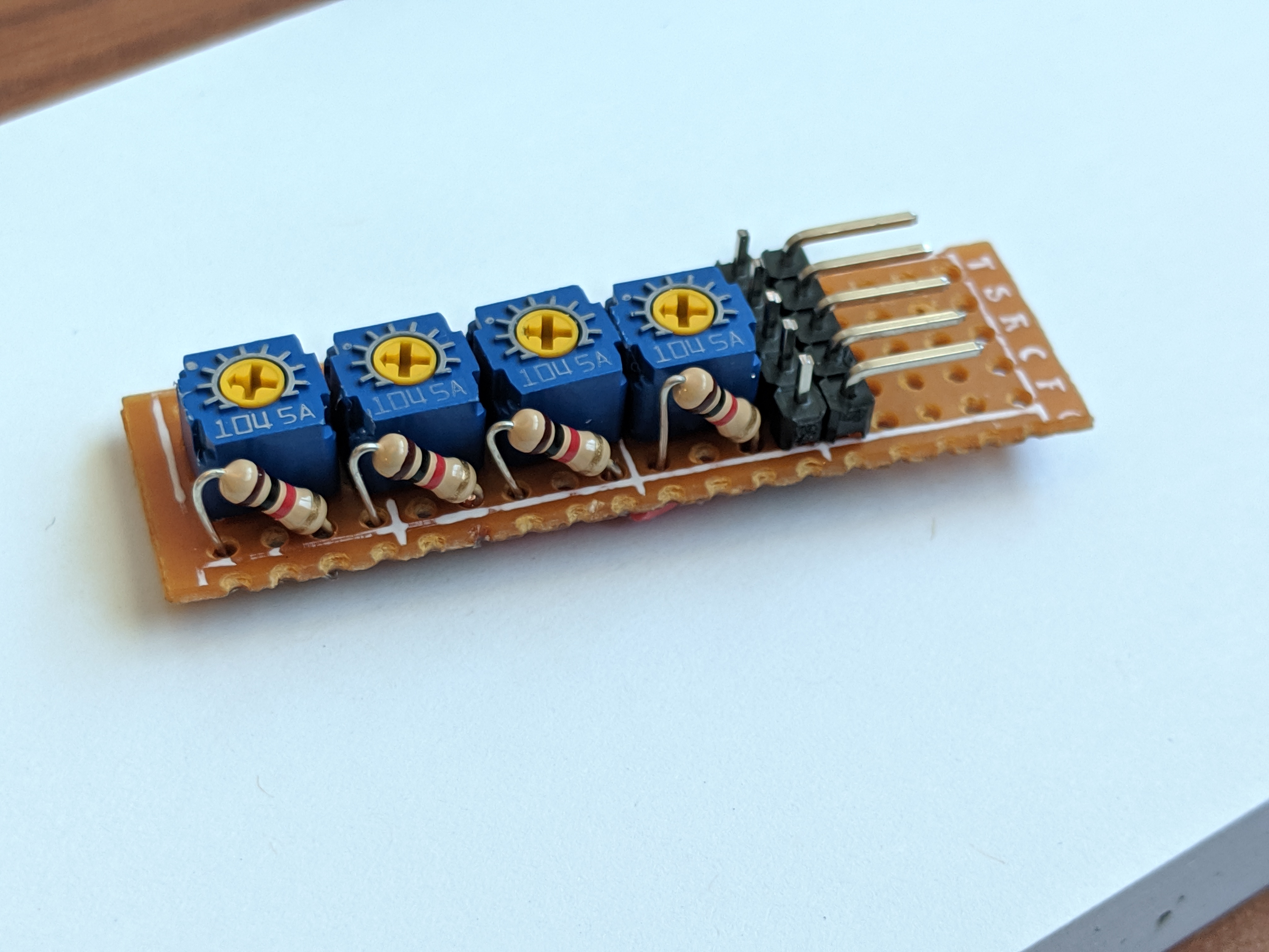
That's just four copies of the trimpot/resistor pair described above, crammed on a piece of matrix board. There are four lines coming in from R6, R7, R8, R9 and one line for common ground--thus five pins on header. I designed it so it can stow away in the mouse here:
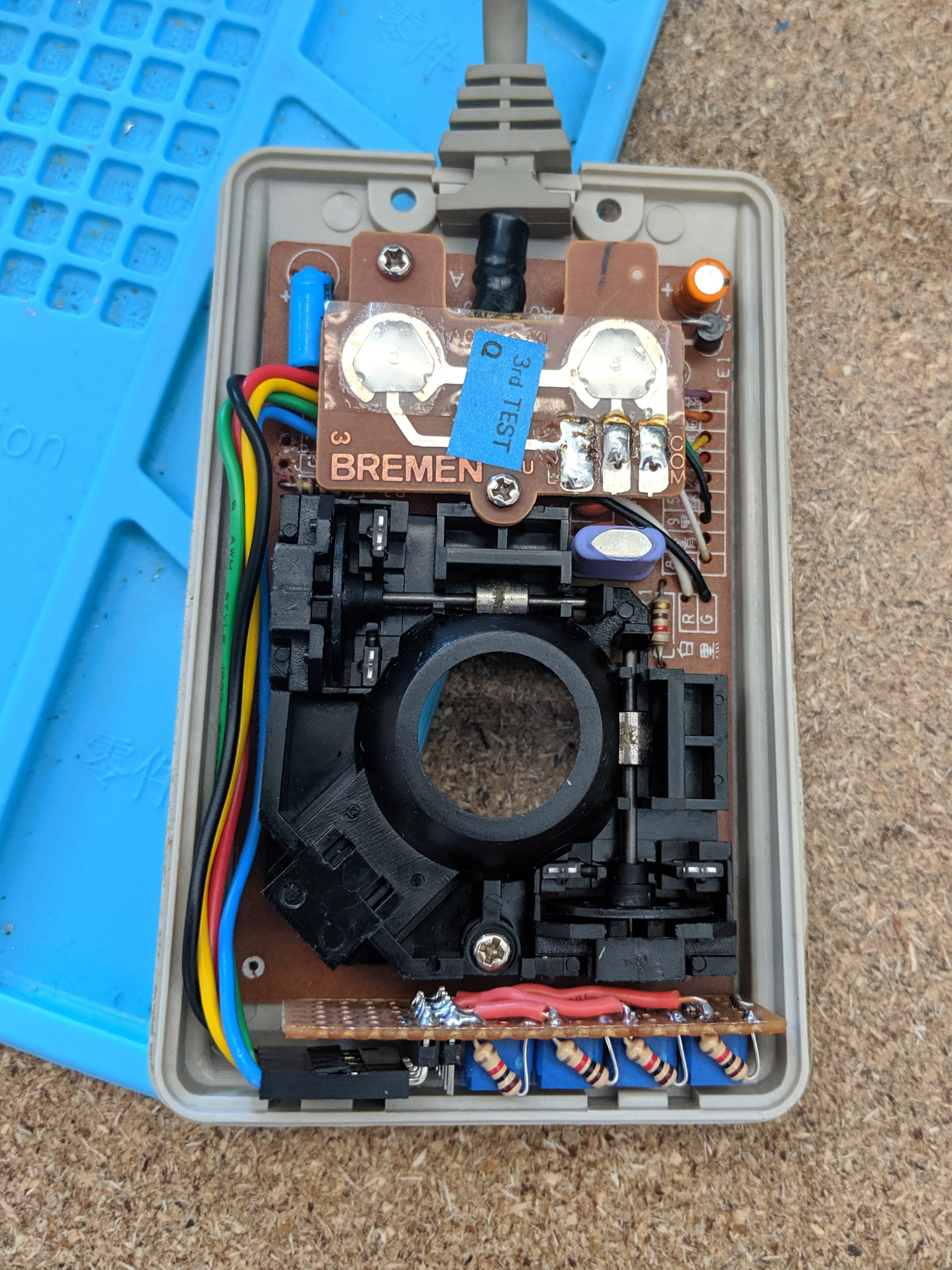
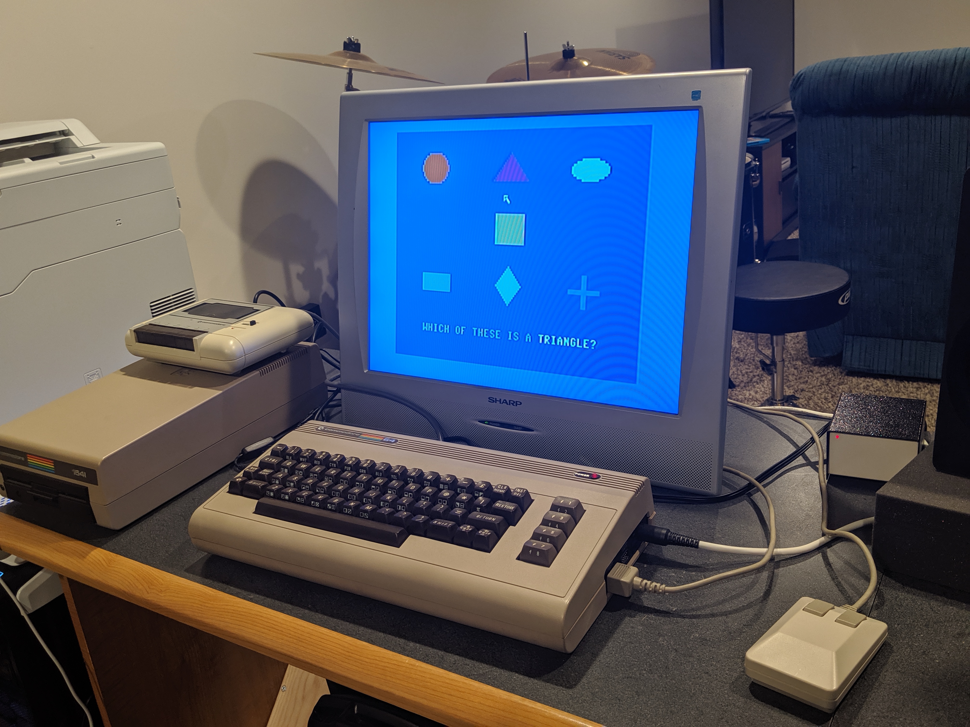
I installed this, tuned the trimpots to get 4.6V on each line, closed up the mouse, and plugged it into my Commodore 64. I booted up the Commodore 1351 Demo Disk, and to my amazement, it worked perfectly!
I'm really happy with this mod, though the underside of the board is not as pretty as the top. Partly this is because I'm a beginner, but wiring on matrix board on something this compact is just tricky.
Another downside is that the board is too wide, so I had to install it sideways. This means the trimpots aren't adjustable with it installed: you have to pull it out, adjust it, and put it back in. It would be nicer if the package could be made narrow enough for the trimpots to face upward.
Making a custom PCB for this, even though the circuit is so simple, could solve both of these problems. I'm tempted. If I end up doing that, I'll update this page.